

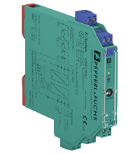
Universal Temperature Converter KCD2-UT2-Ex1
- 1-channel isolated barrier
- 24 V DC supply (Power Rail)
- Thermocouple, RTD, potentiometer or voltage input
- Current output 0/4 mA ... 20 mA
- Sink or source mode
- Configurable by PACTware
- Line fault (LFD) and sensor burnout detection
- Up to SIL 2 acc. to IEC/EN 61508 / IEC/EN 61511


Please note: All product-related documents, such as certificates, declarations of conformity, etc., which were issued prior to the conversion under the name Pepperl+Fuchs GmbH or Pepperl+Fuchs AG, also apply to Pepperl+Fuchs SE.
Technische gegevens KCD2-UT2-Ex1
| General specifications | ||
|---|---|---|
| Signal type | Analog input | |
| Functional safety related parameters | ||
| Safety Integrity Level (SIL) | SIL 2 | |
| Supply | ||
| Connection | terminals 9+, 10- or power feed module/Power Rail | |
| Rated voltage | 19 ... 30 V DC | |
| Ripple | within the supply tolerance | |
| Power dissipation | ≤ 0.98 W | |
| Power consumption | max. 0.98 W | |
| Interface | ||
| Programming interface | programming socket | |
| Input | ||
| Connection side | field side | |
| Connection | terminals 1, 2, 3, 4 | |
| RTD | type Pt10, Pt50, Pt100, Pt500, Pt1000 (EN 60751: 1995) type Pt10GOST, Pt50GOST, Pt100GOST, Pt500GOST, Pt1000GOST (6651-94) type Cu10, Cu50, Cu100 (P50353-92) type Ni100 (DIN 43760) |
|
| Measuring current | approx. 200 µA with RTD | |
| Types of measuring | 2-, 3-, 4-wire connection | |
| Lead resistance | max. 50 Ω per line | |
| Measurement loop monitoring | sensor breakage, sensor short-circuit | |
| Thermocouples | type B, E, J, K, N, R, S, T (IEC 584-1: 1995) type L (DIN 43710: 1985) type TXK, TXKH, TXA (P8.585-2001) |
|
| Cold junction compensation | external and internal | |
| Measurement loop monitoring | sensor breakage | |
| Potentiometer | 0 ... 20 kΩ (2-wire connection), 0.8 ... 20 kΩ (3-wire connection) | |
| Voltage | selectable within the range -100 ... 100 mV | |
| Input resistance | ≥ 1 MΩ (-100 ... 100 mV) | |
| Output | ||
| Connection side | control side | |
| Connection | terminal 5: source (-), terminal 6: source (+), terminal 7: sink(-), terminal 8: sink (+) | |
| Output | Analog current output | |
| Current range | 0 ... 20 mA or 4 ... 20 mA | |
| Fault signal | downscale 0 or 2 mA, upscale 21.5 mA (acc. NAMUR NE43) | |
| Source | load 0 ... 550 Ω open-circuit voltage ≤ 18 V |
|
| Sink | Voltage across terminals 5 ... 30 V. If the current is supplied from a source > 16.5 V, series resistance of ≥ (V - 16.5)/0.0215 Ω is needed, where V is the source voltage. The maximum value of the resistance is (V - 5)/0.0215 Ω. |
|
| Transfer characteristics | ||
| Deviation | ||
| After calibration | Pt100: ± (0.06 % of measurement value in K + 0.1 % of span + 0.1 K (4-wire connection)) thermocouple: ± (0.05 % of measurement value in °C + 0.1 % of span + 1.5 K (1.7 K for types R and S)) , includes ± 1.3 K fault of the cold junction compensation (CJC) mV: ± (50 µV + 0.1 % of span) potentiometer: ± (0.05 % of full scale + 0.1 % of span, (excludes faults due to lead resistance)) |
|
| Influence of ambient temperature | Pt100: ± (0.0015 % of measurement value in K + 0.006 % of span)/K ΔTamb*) thermocouple: ± (0.02 K + 0.005 % of measurement value in °C + 0.006 % of span)/K ΔTamb*)), influence of cold junction compensation (CJC) included mV: ± (0.01 % of measurement value + 0.006 % of span)/K ΔTamb*) potentiometer: ± 0.006 % of span/K ΔTamb*) *) ΔTamb = ambient temperature change referenced to 23 °C (296 K) |
|
| Influence of supply voltage | < 0.01 % of span | |
| Influence of load | ≤ 0.001 % of output value per 100 Ω | |
| Reaction time | worst case value (sensor breakage and/or sensor short circuit detection enabled) mV: 1 s, thermocouples with CJC: 1.1 s, thermocouples with fixed reference temperature: 1.1 s, 3- or 4-wire RTD: 920 ms, 2-wire RTD: 800 ms, Potentiometer: 2.05 s |
|
| Galvanic isolation | ||
| Output/supply, programming input | functional insulation, rated insulation voltage 50 V AC There is no electrical isolation between the programming input and the supply. The programming cable provides galvanic isolation so that ground loops are avoided. |
|
| Indicators/settings | ||
| Display elements | LEDs | |
| Configuration | via PACTware | |
| Labeling | space for labeling at the front | |
| Directive conformity | ||
| Electromagnetic compatibility | ||
| Directive 2014/30/EU | EN 61326-1:2013 (industrial locations) | |
| Conformity | ||
| Electromagnetic compatibility | NE 21:2012 EN 61326-3-2:2008 |
|
| Degree of protection | IEC 60529:2001 | |
| Protection against electrical shock | UL 61010-1:2004 | |
| Ambient conditions | ||
| Ambient temperature | -20 ... 70 °C (-4 ... 158 °F) | |
| Mechanical specifications | ||
| Degree of protection | IP20 | |
| Connection | screw terminals | |
| Mass | approx. 100 g | |
| Dimensions | 12.5 x 119 x 114 mm (0.5 x 4.7 x 4.5 inch) (W x H x D) , housing type A2 | |
| Height | 119 mm | |
| Width | 12.5 mm | |
| Depth | 114 mm | |
| Mounting | on 35 mm DIN mounting rail acc. to EN 60715:2001 | |
| Data for application in connection with hazardous areas | ||
| EU-type examination certificate | BASEEFA 13 ATEX 0102 X | |
| Marking |  II (1)G [Ex ia Ga] IIC , II (1)D [Ex ia Da] IIIC , I (M1) [Ex ia Ma] I II (1)G [Ex ia Ga] IIC , II (1)D [Ex ia Da] IIIC , I (M1) [Ex ia Ma] I |
|
| Input | [Ex ia Ga] IIC, [Ex ia Da] IIIC, [Ex ia Ma] I | |
| Inputs | terminals 1, 2, 3, 4 | |
| Voltage | 9 V | |
| Current | 13.1 mA | |
| Power | 30 mW | |
| Analog outputs, power supply, collective error | ||
| Maximum safe voltage | 250 V (Attention! This is not the rated voltage.) | |
| Interface | ||
| Maximum safe voltage | 250 V (Attention! The rated voltage is lower.), RS 232 | |
| Certificate | BASEEFA 13 ATEX 0103 X | |
| Marking | II 3G Ex nA IIC T4 Gc |
|
| Galvanic isolation | ||
| Input/Other circuits | safe electrical isolation acc. to IEC/EN 60079-11, voltage peak value 375 V | |
| Directive conformity | ||
| Directive 2014/34/EU | EN IEC 60079-0:2018+AC:2020 , EN 60079-11:2012 , EN 60079-15:2010 | |
| International approvals | ||
| UL approval | ||
| Control drawing | 116-0379 (cULus) | |
| IECEx approval | ||
| IECEx certificate | IECEx BAS 13.0057X | |
| IECEx marking | [Ex ia Ga] IIC, [Ex ia Da] IIIC, [Ex ia Ma] I | |
| General information | ||
| Supplementary information | Observe the certificates, declarations of conformity, instruction manuals, and manuals where applicable. For information see www.pepperl-fuchs.com. | |
Classifications
| System | Classcode |
|---|---|
| ECLASS 13.0 | 27210129 |
| ECLASS 12.0 | 27210129 |
| ECLASS 11.0 | 27210129 |
| ECLASS 10.0.1 | 27210129 |
| ECLASS 9.0 | 27210129 |
| ECLASS 8.0 | 27210190 |
| ECLASS 5.1 | 27210107 |
| ETIM 9.0 | EC002919 |
| ETIM 8.0 | EC002919 |
| ETIM 7.0 | EC002919 |
| ETIM 6.0 | EC002919 |
| ETIM 5.0 | EC001485 |
| UNSPSC 12.1 | 32101514 |
Details: KCD2-UT2-Ex1
Datasheet: KCD2-UT2-Ex1
| Datasheet | Bestandstype | Bestandsgrootte |
|---|---|---|
| Datasheet KCD2-UT2-Ex1 | 973 KB | |
| Fiche de données KCD2-UT2-Ex1 | 979 KB | |
| Datenblatt KCD2-UT2-Ex1 | 975 KB | |
| Datasheet KCD2-UT2-Ex1 | 982 KB | |
| Hoja de datos KCD2-UT2-Ex1 | 978 KB |
Documents: KCD2-UT2-Ex1
CAD+CAE: KCD2-UT2-Ex1
| CAD | Bestandstype | Bestandsgrootte |
|---|---|---|
| CAD 3-D / CAD 3-D | STP | 3085 KB |
| CAD Portal / CAD Portal | LINK | --- |
| EPLAN | ||
| CAE EPLAN Data Portal / CAE EPLAN Data Portal | LINK | --- |
| CAE EPLAN macro EDZ / CAE EPLAN Makro EDZ | EDZ | 1690 KB |
Approvals+Certificates: KCD2-UT2-Ex1
| Certificates | Bestandstype | Bestandsgrootte |
|---|---|---|
| China SITIIAS CCC Ex Certificate | 1047 KB | |
| Europe Baseefa II (1) G Group I (M1) II (1) D ATEX Category (1) GD | 557 KB | |
| Europe Baseefa II 3 G ATEX Category 3 G | 457 KB | |
| IECEx Certificate of Conformity | LINK | --- |
| Korea KOSHA | 722 KB | |
| Korea KOSHA | 728 KB | |
| South Africa MASC | 745 KB | |
| USA Canada UL Hazardous Location Certificate of Compliance cULus UL E106378 | 355 KB | |
| Control Drawings | ||
| Control drawing UL / Control drawing UL | 46 KB | |
| Declaration of Conformity | ||
| EU Declaration of Conformity (P+F) / EU-Konformitäterklärung (P+F) | 194 KB |
Software: KCD2-UT2-Ex1
| Device type managers (DTM) | Bestandstype | Bestandsgrootte |
|---|---|---|
| DTM Collection Interface Technology 2 / DTM Collection Interface Technology 2 | ZIP | 32633 KB |
| Software Tools | ||
| PACTware 4.1 SP6 / PACTware 4.1 SP6 | ZIP | 43327 KB |
| PACTware 5.0 / PACTware 5.0 | ZIP | 44203 KB |
Aanverwante producten: KCD2-UT2-Ex1
| Matching System Components | ||||||
|---|---|---|---|---|---|---|
|
||||||
|
||||||
|
||||||
|
||||||
|
||||||
|
||||||
|
||||||
|
||||||
|
||||||
| Accessories | ||||||
|
||||||
|
||||||
|
||||||
|
||||||
|
||||||
|
||||||


Choose from various selection criteria like safety integrity level, performance level, device function, and signal type and find the SIL/PL assessed device that you are looking for.


Pepperl+Fuchs B.V.
Pettelaarpark 104
5216 PR 's-Hertogenbosch
Nederland
sales@nl.pepperl-fuchs.com
 +31 73 75 07 107
sales-pa@nl.pepperl-fuchs.com
+31 73 75 07 108
Pepperl+Fuchs is een toonaangevend ontwikkelaar en producent van elektronische sensoren en componenten voor de wereldwijde automatiseringsmarkt. Continue innovatie, hoge kwaliteit en gestage groei zijn de basis van ons succes, al meer dan 70 jaar. Pepperl+Fuchs heeft wereldwijd 6300 medewerkers en productiefaciliteiten in Duitsland, de Verenigde Staten, Singapore, Hongarije, Indonesië en Vietnam, waarvan het merendeel ISO 9001 gecertificeerd.