

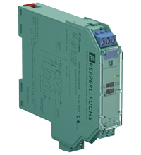
Voltage Repeater KFD2-VR2-Ex1.50M
- 1-channel isolated barrier
- 24 V DC supply (Power Rail)
- Voltage input 0 mV ... ± 50 mV
- Voltage output 0 mV ... ± 50 mV
- Selectable up/downscale sensor breakage detection


Please note: All product-related documents, such as certificates, declarations of conformity, etc., which were issued prior to the conversion under the name Pepperl+Fuchs GmbH or Pepperl+Fuchs AG, also apply to Pepperl+Fuchs SE.
Technische gegevens KFD2-VR2-Ex1.50M
| General specifications | ||
|---|---|---|
| Signal type | Analog input | |
| Supply | ||
| Connection | Power Rail or terminals 14+, 15- | |
| Rated voltage | 19 ... 30 V DC | |
| Ripple | within the supply tolerance | |
| Rated current | ≤ 11 mA | |
| Power dissipation/power consumption | 0.3 W max. | |
| Input | ||
| Connection side | field side | |
| Connection | terminals 4+, 5- | |
| Input resistance | min. 20 MΩ | |
| Transmission range | -50 ... 50 mV | |
| Offset voltage/current | ≤ 5 µV / ≤ 5 nA | |
| Line fault detection | 100 nA | |
| Output | ||
| Connection side | control side | |
| Connection | terminals 7+, 8- | |
| Voltage | -50 ... 50 mV | |
| Load | Accuracy figures for infinite load impedance. Additional 0.03 % of span for a load resistance of 10 kΩ | |
| Fault signal | sensor breakage: > +100 mV (upscale), < -100 mV (downscale) | |
| Output resistance | max. 3 Ω | |
| Transfer characteristics | ||
| Cut-off frequency | 350 Hz (-3 dB) | |
| Deviation | ||
| After calibration | at 20 °C (68 °F): ± 3 µV up to ± 10 mV/± 0.03 % of the span up to +50 mV/± 0.05 % of the span up to -50 mV | |
| Influence of ambient temperature | ± 1 µV/K (typical ± 0.25 µV/K) | |
| Absolute | < 0.25 K at 30 V voltage supply | |
| Rise time | ≤ 1 ms | |
| Galvanic isolation | ||
| Output/power supply | functional insulation, rated insulation voltage 50 V AC | |
| Indicators/settings | ||
| Display elements | LED | |
| Control elements | DIP switch | |
| Configuration | via DIP switches | |
| Labeling | space for labeling at the front | |
| Directive conformity | ||
| Electromagnetic compatibility | ||
| Directive 2014/30/EU | EN 61326-1:2013 (industrial locations) | |
| Conformity | ||
| Electromagnetic compatibility | NE 21:2006 | |
| Degree of protection | IEC 60529:2001 | |
| Protection against electrical shock | UL 61010-1 | |
| Ambient conditions | ||
| Ambient temperature | -40 ... 60 °C (-40 ... 140 °F) extended ambient temperature range up to 70 °C (158 °F), refer to manual for necessary mounting conditions |
|
| Mechanical specifications | ||
| Degree of protection | IP20 | |
| Connection | screw terminals | |
| Mass | approx. 125 g | |
| Dimensions | 20 x 119 x 115 mm (0.8 x 4.7 x 4.5 inch) (W x H x D) , housing type B2 | |
| Height | 119 mm | |
| Width | 20 mm | |
| Depth | 115 mm | |
| Mounting | on 35 mm DIN mounting rail acc. to EN 60715:2001 | |
| Data for application in connection with hazardous areas | ||
| EU-type examination certificate | BASEEFA 06 ATEX 0040 | |
| Marking |  II (1)G [Ex ia Ga] IIC II (1)D [Ex ia Da] IIIC I (M1) [Ex ia Ma] I II (1)G [Ex ia Ga] IIC II (1)D [Ex ia Da] IIIC I (M1) [Ex ia Ma] I |
|
| Voltage | 5.5 V DC | |
| Current | 2.4 mA | |
| Power | 3.3 mW | |
| Supply | ||
| Maximum safe voltage | 250 V (Attention! The rated voltage can be lower.) | |
| Certificate | BASEEFA 09 ATEX 0219X | |
| Marking | II 3G Ex ec IIC T4 Gc |
|
| Galvanic isolation | ||
| Input/Output | safe electrical isolation acc. to IEC/EN 60079-11, voltage peak value 375 V | |
| Input/power supply | safe electrical isolation acc. to IEC/EN 60079-11, voltage peak value 375 V | |
| Directive conformity | ||
| Directive 2014/34/EU | EN IEC 60079-0:2018+AC:2020 , EN IEC 60079-7:2015+A1:2018 , EN 60079-11:2012 | |
| International approvals | ||
| UL approval | E106378 | |
| Control drawing | 116-0334 (cULus) | |
| IECEx approval | ||
| IECEx certificate | IECEx BAS 06.0011 IECEx BAS 09.0103X |
|
| IECEx marking | [Ex ia Ga] IIC , [Ex ia Da] IIIC , [Ex ia Ma] I Ex ec IIC T4 Gc |
|
| General information | ||
| Supplementary information | Observe the certificates, declarations of conformity, instruction manuals, and manuals where applicable. For information see www.pepperl-fuchs.com. | |
Classifications
| System | Classcode |
|---|---|
| ECLASS 13.0 | 27210125 |
| ECLASS 12.0 | 27210120 |
| ECLASS 11.0 | 27210120 |
| ECLASS 10.0.1 | 27210120 |
| ECLASS 9.0 | 27210120 |
| ECLASS 8.0 | 27210120 |
| ECLASS 5.1 | 27210120 |
| ETIM 9.0 | EC002653 |
| ETIM 8.0 | EC002653 |
| ETIM 7.0 | EC002653 |
| ETIM 6.0 | EC002653 |
| ETIM 5.0 | EC001485 |
| UNSPSC 12.1 | 32101514 |
Details: KFD2-VR2-Ex1.50M
Datasheet: KFD2-VR2-Ex1.50M
| Datasheet | Bestandstype | Bestandsgrootte |
|---|---|---|
| Datasheet KFD2-VR2-Ex1.50M | 1089 KB | |
| Fiche de données KFD2-VR2-Ex1.50M | 1094 KB | |
| Datenblatt KFD2-VR2-Ex1.50M | 1090 KB | |
| Datasheet KFD2-VR2-Ex1.50M | 1098 KB | |
| Hoja de datos KFD2-VR2-Ex1.50M | 1092 KB |
Documents: KFD2-VR2-Ex1.50M
CAD+CAE: KFD2-VR2-Ex1.50M
| CAD | Bestandstype | Bestandsgrootte |
|---|---|---|
| CAD 3-D / CAD 3-D | STP | 2510 KB |
| CAD Portal / CAD Portal | LINK | --- |
| EPLAN | ||
| EPLAN macro EDZ / EPLAN Makro EDZ | EDZ | 57 KB |
Approvals+Certificates: KFD2-VR2-Ex1.50M
| Certificates | Bestandstype | Bestandsgrootte |
|---|---|---|
| Australia Test Safe | 6788 KB | |
| Baseefa IECEx Certificate of Conformity | LINK | --- |
| Baseefa IECEx Certificate of Conformity | LINK | --- |
| Brasil TUV Rheinland Brazil | 1140 KB | |
| Canada UL cUL | LINK | --- |
| Canada UL cUL | LINK | --- |
| China SITIIAS CCC Ex Certificate | 1069 KB | |
| Europe Baseefa II (1) D I (M1) II (1) G | 269 KB | |
| Europe Baseefa II 3 G | 253 KB | |
| Japan TIIS | 1632 KB | |
| Korea KOSHA | 895 KB | |
| USA UL | LINK | --- |
| USA UL | LINK | --- |
| United Kingdom UKEX Category (1) G UK-Type Examination Certificate UKEX Category (M1) UKEX Category (1) D | 186 KB | |
| Control Drawings | ||
| Control drawing UL / Control drawing UL | 52 KB | |
| Declaration of Conformity | ||
| EU Declaration of Conformity (P+F) / EU-Konformitäterklärung (P+F) | 83 KB |
Aanverwante producten: KFD2-VR2-Ex1.50M
| Matching System Components | ||||||
|---|---|---|---|---|---|---|
|
||||||
|
||||||
|
||||||
|
||||||
|
||||||
|
||||||
| Accessories | ||||||
|
||||||
|
||||||
|
||||||


Choose from various selection criteria like safety integrity level, performance level, device function, and signal type and find the SIL/PL assessed device that you are looking for.


Pepperl+Fuchs B.V.
Pettelaarpark 104
5216 PR 's-Hertogenbosch
Nederland
sales@nl.pepperl-fuchs.com
 +31 73 75 07 107
sales-pa@nl.pepperl-fuchs.com
+31 73 75 07 108
Pepperl+Fuchs is een toonaangevend ontwikkelaar en producent van elektronische sensoren en componenten voor de wereldwijde automatiseringsmarkt. Continue innovatie, hoge kwaliteit en gestage groei zijn de basis van ons succes, al meer dan 70 jaar. Pepperl+Fuchs heeft wereldwijd 6300 medewerkers en productiefaciliteiten in Duitsland, de Verenigde Staten, Singapore, Hongarije, Indonesië en Vietnam, waarvan het merendeel ISO 9001 gecertificeerd.